lab-environment-setup-using-gns3
This section outlines the setup of a virtual lab environment using GNS3 to simulate a network suitable for SNMP monitoring and security testing. The topology includes routers, switches, virtual machines, and PCs to emulate real-world monitoring scenarios.
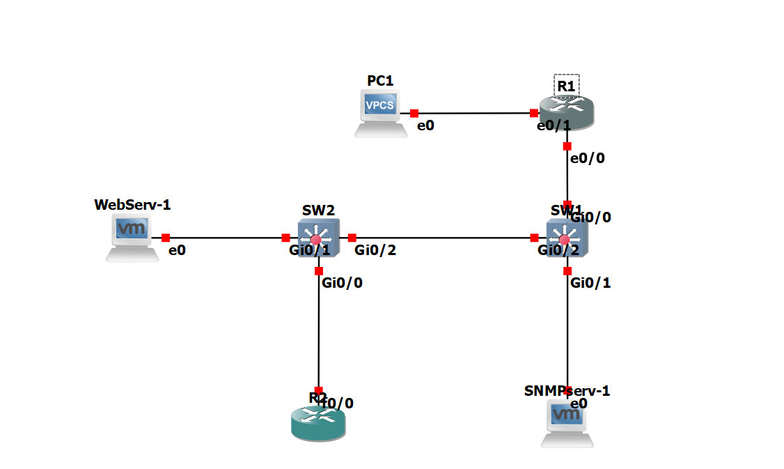
1 Overview of the Lab Topology
The lab topology consists of the following components:
- R1 and R2: Two cisco routers.
- SW1 & SW2: Layer 2 switches used to connect end devices and route traffic within the topology.
- PC1: A virtual PC (VPCS) used for issuing SNMP queries and simulating user activity.
- WebServ-1: A Linux-based VM acting as a server.
- SNMPServ-1: A kali Linux VM dedicated to SNMP operations such as packet capturing, brute force testing, and testing SNMP configuration.
| Device | Interface | IP Address |
|---|---|---|
| R1 | e0/0 | 10.0.0.253/24 |
| R1 | e0/1 | 10.0.1.254/24 |
| R2 | f0/0 | 10.0.0.254/24 |
| SW1 | VLAN 1 | 10.0.0.100/24 |
| SW2 | VLAN 1 | 10.0.0.200/24 |
| SNMP-Serv | eth0 | 10.0.0.1/24 |
| WebServ | eth0 | 10.0.0.4/24 |
| PC1 | eth0 | 10.0.1.1/24 |
The layout supports both basic SNMP interactions and security experiments including traffic interception and brute force attacks.
2 Tools and Software Requirements
To replicate this lab, the following tools and software are required:
- GNS3
- Cisco router and switch images
- GNS3 VM or local server for VM integration
- Linux VM images (e.g., Ubuntu or Debian-based for SNMP and Flask setup)
- VPCS for lightweight PC simulation
- Wireshark for traffic analysis
- SNMP utilities (snmpwalk, snmpget, snmp-check, etc.)
- Python 3.7 and Flask framework for the web application